All ways to generate symmetrical rails from a single SMPS
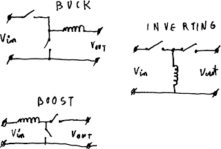
Introduction While digital systems are increasingly taking over the world, analog circuits are still used in many places, especially in musical equipment. Most of these devices use symmetrical power rails to simplify internal construction. While such approach is indeed good for devices powered from mains with a transformer, it fails short when supplied from a single DC source like battery. In a current world where many devices are getting smaller and more portable, this design philosophy becomes a limiting factor. While we can't change already created devices, we can create a simple switching mode power supply to generate symmetrical power rails from a single DC source. Theoretical implementations There are many ways to generate multiple output rails from a single DC source. Listed in decreasing popularity: Flyback converter with multiple secondary windings Two independent converters (inverting and buck or boost) Inverting converter based on coupled inductor with rectifier p...