Implementing FIR on RP2040's PIO
Introduction
In my latest research I'm in need to connect MEMS microphone with Pulse Density Modulation (PDM) to micro-controller to evaluate their parameters. In contrary to more popular Pule Code Modulation (PCM) that sends data at reasonable sample rate (40-192khz) with wide words (8-24 bits) PDM sends one bit stream at Mhz sample rate straight from sigma-delta modulator. To do anything useful with this stream it needs to be decimated to lower sample rate while increasing word width and filtering out high frequency noise.
My microphone generates PDM stream at around 3Mhz. I want to downsample it around 40khz to feed my "standard" software DSP to have enough time to process data.
Why?
Decimating signal is as simple as selecting one sample every N and dropping rest. In order to not alias frequencies above new Nyquist frequency it's important to properly low pass filter input signal prior to decimation. Otherwise high frequencies are gonna "reflect" around Nyquist frequency and interfere with in band signals. As sigma-delta modulators tand to shape quantization noise into higher frequencies it's critical to remove everything that will alias into 0-20khz range.
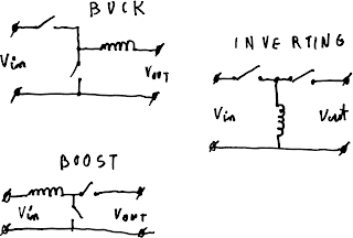
At low frequencies FIR filters are used to get sharp cutoffs and little in-band amplitude distortion but at such high frequencies it's unfeasible to calculate convolution directly. Instead degenerate cases are used that are much faster. The one I focused at is CIC filter also called moving average. It can be calculated quite quickly with just 2 additions and delay line. By cascading multiple stages sharp low pass can be created.
rp2040 can run at up to 133Mhz which means it has around 44 cycles per input sample. While it's probably enough to implement 6 order CIC filter I need I decided to dedicate as much work to hardware as possible and because I'm implementing PDM peripheral in PIO my first thought was to do as much low pass filtering there as possible.
Initial solution
At first I recalled encoder example. It stores 4 bit word with previous and current encoder state and uses computed jump table to decide what action to take. I tried same approach with storing last 4 bits from microphone and doing computed jump to get the result. Unfortunately I didn't manage to find a way to jump to set instructions, instead I set x register to max output value and jump to array of jump statements that subtract one form x register (or don't if it's max value look-up) and then jump to correction set of subtracting jumps that further subtract from x to get required value. Due to instruction limit the FIR can be at most of order 4 (because we have 32 instructions so jump table can be at most 16 entries) and sum of coefficients can be at most 6 (or 8 if second PIO is used to generate sync signals).
The problem is that 4 point FIR filter is quite bad at filtering so it's more of a coarse shaper to increase top stopband by few dB than meaningful filter.
Better solution
If I just want to implement moving average filter with no weights (equal to FIR with all coefficients being 1) I don't need to store coefficients and changing processing I can work with up to 32 bit long filters. every wrap I shift one new input bit into ISR, that way ISR contains last 32 bits. Then I move ISR to OSR and loop 32 times every time shifting one bit to y register. Then program branches in loop depending on state of y register conditionally decrementing total count. In the end I get popcount of ones in ISR.
Slight problem is that ISR contains shifted data and so has to be excluded from counting, OSR is used for shifting data, one of scratch registers is used for bit selection and the other for counting ones. There's nothing left to implement loop counter! This can be solved by branching on !OSRE, it can be used to track when we're done with all 32 bits (or really any bit count that is set as autopull) only requiring one pull with NOBLOCK flag (as there's obviously nothing in TX queue).
Further optimization
CIC filter is composed of integrator, block that accumulates all input samples. It just so happens that rp2040 DMA's sniffer block is capable of accumulating (summing) all processed samples. To use that 3 DMA channels have to be configured in quite peculiar way. DMA1 has DREQ connected to PIO RX FIFO, read address to to RX FIFO, write address to some dummy in memory and transfer size to 1. It's chained to DMA2 that reads from sniffer's accumulator address and writes to array, also with transfer size of 1. Finally DMA2 is chained to DMA3 that copies control blocks from array to DMA1 configuration. After predefined amount of blocks (that just trigger DMA1) it has control block with all zeros, so called null trigger that triggers interrupt letting microcontroller know that there's data to process.
Further work
While reading documentation for rp2040 for some time I hoped there's separate sniffer for every DMA channel and I could just chain DMAs to get higher order integrator. Unfortunately there's just one sniffer onboard. In theory it'd be possible to make complex DMA control block chain that sends data through integrating DMA once, reloads sniffer's accumulator with next integrator's last value, changes DMA1&2 read and write pointers and reruns calculations to get higher order integration. Problem is that it takes quite some time to set everything up so to amortize the cost big buffers would need to be used inquiring big latency.
Is it worth it?
Honestly I don't know. The PIO filter is probably good idea as it costs near nothing. On the other hand DMA magic adds a lot of bus traffic hence making realtime operation a bit harder and less predictable. It also consumes a lot of memory. For every byte of sum it requires 4 bytes of configuration array.
Comments
Post a Comment