soalr SMPS part 2: output driver
Today we'll focus on LED driving part. First let's write down what we already know:
- 0.3-1A output current (for 1-3W output power respectively)
- 2.2-2.8V output voltage (depends on the color and power)
- 3-4.2V input voltage (li-ion cell)
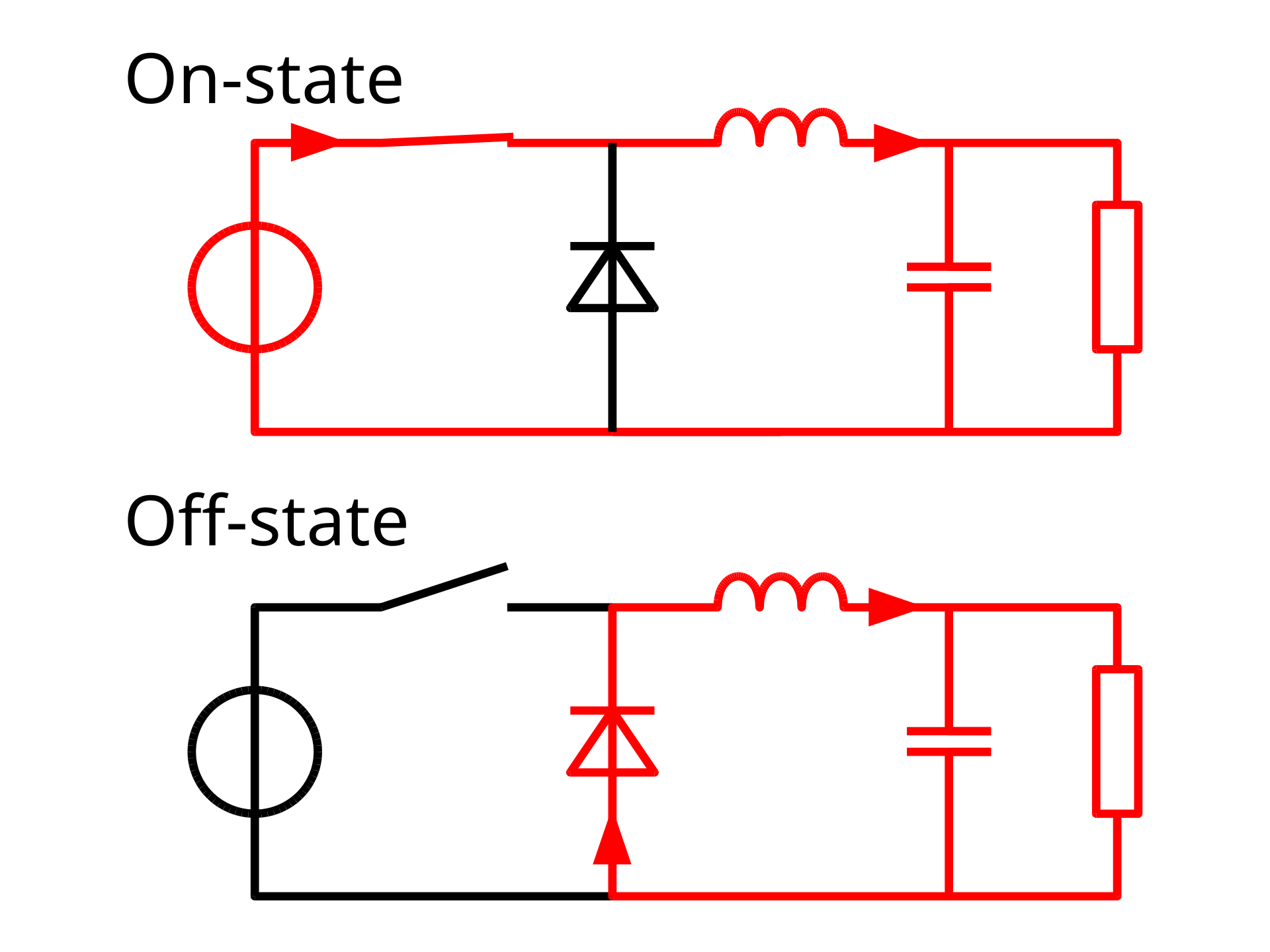
As we can see SMPS needs to step down voltage. This can be achieved using a simple buck converter.
 |
| source: wikipedia |
This diagram shows an idealized buck converter. The idea is simple - we pass current through load "dropping" voltage on an inductor and when we open the switch, the inductor forces additional, "free" current through load with a help of a diode. Only thing left is to chose the best elements for this application: switch, diode, inductor and output capacitor.
Switch
For switch, I decided to use MOSFET. The switching element passes load current for 52-93% of cycle (calculations will be discussed later) and dissipates power due to internal resistance. It's trivial now that we want this resistance to be the lowest possible. In general n channel MOSFETs have better specs than p channel MOSFETs. On the other hand, high side switching with p channel MOSFET is a straightforward operation, and for n channel mosfet special bootstrapping is required. I decided to use p channel MOSFET as switch, and I found CSD25310Q2 as being the best candidate. Assuming only 3V of Vgs, it has typical Rds=24mohm, which is the worst case (3W 1A 93%) and represents total loss of 0.93*1A*1A*0.024 ohm = 22mW.
There's one more place where power gets lost - charging and discharging gate. If we assume switching frequency is 1Mhz and take a typical gate charge from the datasheet, 3.5nC, we get switching power loss of a 7mW. That would mean in total we loss 0.98%.
Diode
As diode I chose Schottky junction part due to its faster switching, lower stored charge and lower forward voltage. The best diodes should have the lowest possible forward voltage at a given current and the lowest possible switching charge. As usually, these 2 parameters exclude each other, so a right balance needs to be found depending on a switching frequency and an acceptable price.
I chose NSR20F20 as my rectifying diodes. Not being entirely sure about the final switching frequency, I decided to put 2 footprints on PCB and populate the second one while testing. I discovered that at 25C, 1A diode has a voltage drop of 0.4V, which gets smaller when it heats up.
Inductor
There are 2 important inductor parameters we need to focus on: resistance and inductance. Resistance represents the power loss due to an finite conductance of wire used for making the inductor. Inductance defines how much inductor resist current changes, how slowly it will rump the current up or down. For a given price R/L ratio is roughly constant. We want to minimize resistance (to minimize losses), and for that we need to minimize rquired inductance. Yet inductance is a thing that stabilizes the output current. If we reduce inductance, we'll increase the current ramp speed and we'll need to increase switching frequency. Clearly there's a sweet-spot somewhere.
Let's now try to calculate the needed inductor. Assuming we'll be working in DCM mode (explained later), max current will be >2x load current. This means that the saturation current needs to be over 2A. Since I want it to work at the edge of CCM and DCM, so in one period our current ramps from 0 to max, and down back to 0. Assuming 2V on LED and 4V on battery (for sake of calculations), we obtain IL=TU. Solving for L we get 3.3uH as our smallest inductor. Bigger inductor will push more and more of our working range into CCM. I did math for a few more cases during a free time. And I found that 10uH is critical inductance to cover the entire work range in CCM.
 |
| Even more math for more cases |
I decided on Bourns SRU1048 series. Particularly on 3 inductors:
- SRU1048-100Y. 10uH, 3.7A saturation, 18.5mR
- SRU1048-150Y 15uH, 2.7A saturation, 29mR
- SRU1048-220Y 22uH, 2A saturation, 42mR
This specific selection is influenced by one simple fact. All 3 inductors have the same footprint, so it'll be easy to swap them and I have all of them at home, so I won't be disturbed by supply chain issues. My prediction is 10uH will perform better, and maybe even a bit smaller inductor will be needed.
For the sake of calculations let's take an 10uH inductor and Irms of 1.3A. This would give power loss is 29.6mW or approximately 1%.
Capacitor
In fact, the capacitor only really regulates output ripple only so I'll choose it at the end to meet the ripple criteria.
Capacitor smooths the output voltage, "taking away" some ripple from the diode. I don't like diodes blinking at high frequencies, so this capacitor will be chosen to reduce ripple as much as possible without introducing too much phase shift (group delay) into the feedback loop.
Final notes
Technically, 3W white LEDs have forward voltage of over 3V, so we can't drive them at the full power within an entire input range. At a first glance, it seems to be an odd decision in spite of trying to achieve an ultimate efficiency. I tried designing a back-boost topology to be able to drive all sorts of LEDs (mostly with UV excited white LEDs in mind), but calculations showed that I would lower the efficiency in most cases, so it won't be included in this version.
Comments
Post a Comment