Soalr SMPS Part 3: Improvments In Output Driver
As we've seen last time the biggest power loss is due to diode's forward voltage. In this post, I'll try to substantially reduce it.
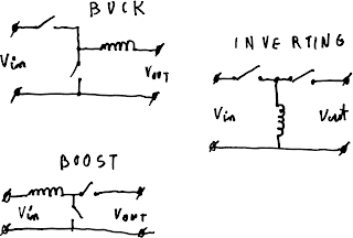
Synchronous converter
Let's look for a second at a bit different converter topology. If I substitute another switch (n channel mosfet for eg.) instead of diode, and switch it "just the right way", we can reduce power loss significantly. Power loss will be given by RI^2 and will be dependent only on the resistance of switch which, with modern MOSFETs, can be remarkably small. The only minor problem is driving this switch "just the right way". We need to make sure we don't turn both MOSFETs on at the same time, as this would be equivalent to shorting a battery. We also need to sense when the current drops to zero and turn off because otherwise it will reverse and will start pulling the power from load capacitor back to inductor and upon turning off the switch send it back to the battery via internal an diode of p channel MOSFET.
 |
| synchronous converter schematic |
Synchronous converter would increase the efficiency a lot. Instead of >6% lost on diodes, we could loss as little as 0.3%. Like for all other perfect things, devil's in the details, and here, this detail is found in current sensing.
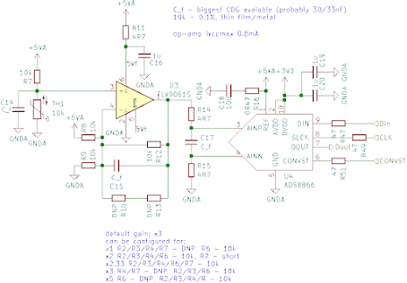
One way would be to introduce small resistor between source and ground and measure voltage there. Obvious downside is power loss on resistor, offsetting advantage of this solution. Other solution would be to use Rds of switching mosfet itself to measure current. That has upside of no additional power loss, but creating high gain, low offset amplifier with high enough bandwidth, that won't saturate for too long when switch opens and voltage goes as high as Vds=4.2V while drawing little current itself proved to be very hard. We could use dedicated IC but they tend to be expensive and a little to power hungry for this.
Semi-synchronous converter
I won't lie. I made this name up, never seen this device literature so I had to name it somehow. The the main idea is to get best of both converters. Low power loss of synchronous design while keeping ease of switching of diode.

If we introduce back diode and keep the mosfet we can divide rectifying part into 2 regions. (We call rectifying sending this "free" current to load somehow). When current is high we use mosfet to reduce power loss turning it off after some predetermined time when current is low but still positive letting diode do rest of the work. This way we can be sure we don't pull power from load while still closing high currents with low loss.
Pros:
- As the current ramp is roughly linear getting mosfet on for just half of conduction time reduces power lost in diode by 75% (loss in mosfet is negligible)
- no need to measure inductor current
- Even if mosfet slowly opens Vds is limited to Vf of diode. (no losses due to slow turn off, it's easier to avoid shorting battery)
- in dead time (when both mosfets are closed) voltage doesn't spike, because diode does it's work (less EMI).
- diode needs to carry less current load so can be smaller and of smaller capacitance (smaller power losses)
Cons:
- As we have no feedback we're basically guessing how long the mosfet needs to be on.
- As turning mosfet on for too long kills efficiency very fast we need to be very conservative in our estimate.
- we need 2 parts in BOM
Now by the magic of math we know that ratio of upper mosfet closed time to bottom mosfet closed time is Uo/(Ui-Uo). Assuming highest possible output voltage of 2.8V we can plot this ratio for all input voltages.
 |
| t lower / t upper in terms of supply voltage |
 |
| piecewise linear approximation |
It seems that this approximation wouldn't bring a lot of benefits but it's worth keeping in mind that current is not equal in this conduction time but drops linearly.
 |
| % loss relative to no mosfet case |
The increasing loss below 3.1V is due to too high on cycle of mosfet and while the losses increase they're increasing faster then in my sloppy math. As we can see even such simple approximation reduces losses in worst case to just 47% while average loss gets reduced to 15.4%. 15.4% of 6.4% gives us final loss of 0.98%. That excludes switching loss due to resistance and gate charging and discharging. But even assuming losses as bad as in p channel mosfets (generally n channel mosfets have lower gate charge and Rdson) we get total loss <2%. 3 times better than before.

Comments
Post a Comment