Active Eurorack busboard
Task
Last summer I was asked to design busboard for 3U 42HP eurorack case. For those of you who have no idea what it is I explain. Eurorack system uses 10 (less common) or 16 (more common) pin IDC ribbon to transfer it's power. It requires symmetrical 12V and sometimes 5V. 1HP is 5.08mm so 42HP case roughly 213mm in size.
 |
| source: doepfer.de |
Requirements
As with all project I got set of requirements that contradicted each other partially:
- fit into shape of case, allocating space for 28 M2.5 mounting holes
- provide at least 0.8A on all 3 output rails, 1A on positive rials preferable
- lowest possible output noise
- single 24V input supply
- possibility of daisy chaining
- cooling to top side of PCB
Initial plan
First I started thinking that I can simply use linear regulators for 5V and 12V, but after finding out that I'd need to dissipate over 23W of heat worst case it became immediately obvious it's not the way to go. Case is plastic, without many ventilation holes and without forced cooling so my heat dissipation was very limited.
Switching mode converters
As I described in soalr project step down, buck converters come in two main flavors: synchronous and asynchronous. Synchronous converters have slightly higher efficiency which would help heat problem. If all switching elements are integrated within IC then hot loop is also much smaller, simplifying interference mitigations.
Switching mode converters have one big downside - switching noise.And choosing this frequency is not trivial. The higher the frequency the smaller inductor and filtering capacitors need to be, filtering requires less components and they can be much smaller. On the other hand parasitic inductances start to play bigger and bigger role, electrolytic capacitors become useless due to their ESL, layout gets more and more critical and switching loses increase.
Choosing elements
Considering temperatures in cases and required lifetime of device I ruled out electrolytic capacitors. I'd need to search for expensive high temperature, low ESL models and high capacitance MLCCs aren't that expensive anyway. As output ripple and noise was of utter importance I opted for highest possible switching frequency. With that in mind I went hunting on mouser.
After some time searching I settled on LMR50410. It comes in many variants with 3 main parameters:
- FPWM or PFM which stands for forced PWM or pulse frequency modulation
- 2.1Mhz or 700khz
- fixed or adjustable
PFM mode lowers switching frequency, moving to discontinuous conversion mode when there's small load to reduce power consumption. Unfortunately it also makes output regulation worse and makes output filtering much harder so I've chosen FPWM variant. It shouldn't matter that much unless someone is running case with just one or two power efficient modules.
I've chosen 2.1Mhz model to keep with my promise of choosing highest possible switching frequency. I've also chosen adjustable variant for both 12V and 5V regulators to keep just one IC in BOM.
Heat and how to get rid of it
Datasheet shows efficiency of around 85% for stepping 24V->5V. Conversion efficiency for 24V->12V is not specified but knowing that it has to be higher than 24V->5V I assumed worst case of also 85%. That means 17.5% ((100-85)/85) of output power is heat generation power or around 3W maximum. That's quite some improvement over linear solution.
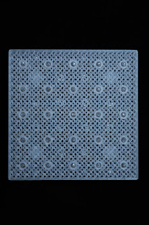
All reference designs for SMPSes assume that you have ground plane at the bottom and you can dissipate heat into it. Unfortunately in this case back is fully covered with plastic so the only way for backside to dissipate heat is to move heat through 1.8mm of FR4 to top layer and dissipate it from there. This is very suboptimal because FR4 has terrible heat transfer characteristics. To solve that I connected IC to as many big planes at the top as possible. Ground connection is not going directly to via to under side but also to ~130mm^2 ground plane at the top layer, input power is also distributed using quite thick plate that get's thinner just next to IC (as thermal relief). In my tests IC-air temperature difference is less than 20C.
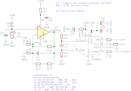
 |
| positive voltage converter PCB design |
Missing -12V
Aside about current modes
Negative rails are harder to make, but to explain why we need to step back and talk a bit more about switching mode converters. There's thing called continuous or discontinuous current. It basically means if current is suddenly changing withing period.
Back when we talked about buck converters for soalr project I said that CCM is better than DCM because it makes output ripple smaller. If current is continuous that means RMS ripple current has to be smaller then average (DC) current, opposite holds true for discontinuous current.
But that's not that important. Ripple current can be filtered out using enough capacitors. What's more problematic is fast transients generated by sudden switching of current. Due to very sharp edges involved they're much harder to cope with. PCB traces have to be considered transmission lines, lead inductance plays dominant role even in 0805 SMD capacitors. Discontinuous output current would make my work so much harder and more irritating.
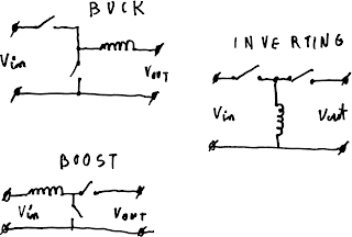
Buck converter can operate in state when output current is continuous (inductor current never dropping to zero) but input current has to be discontinuous because every time we open S1 the input current has to drop to zero.
 |
| source: wikipedia |
This is very handy for us because it means that input ripple will be higher than output ripple. We want clean output voltage and we don't care much about input voltage (as it's not used for anything sensitive).
Unfortunately if we do the same analysis for popular inverting converter (buck-boost). We'll see that it has opposite characteristics. Continuous input current and discontinuous output current.
|
| source: wikipedia |
Flyback converter, other popular and cheap choice used to generate any voltage from any other voltage has discontinuous both input and output currents.
 |
| source: wikipedia |
more complex converters
Trying to find continuous output current converter I had to dig dipper, much dipper. I found two converters that invert voltage and have continuous output current: Weinberg and Cuk. Unfortunately both of them require coupled inductors (transformer) which increases cost significantly. Also ready made ICs for controlling this more complex converters cost significantly more. Lastly due to more inductors and their series resistance efficiency suffers.
Final choice
At last I settled on MAX17577/MAX17578. As before one of them is PFM and one is FPWM model (here called CCM and DCM). I've chosen MAX17577. Datasheet never mentions what type of converter this is but due to grounded inductor I assumed it's simple inverting buck-boost converter. As it later turned out I was only partially correct. It has more complex voltage/current curves than anticipated from such topology and I'm afraid I wasn't able to crack that mystery.
What caught my eye when selecting this converter is 2.2Mhz max switching frequency. Unfortunately after reading datasheet exactly and calculating all necessary component values I realized that this 2.2Mhz is available only for very specific set of output currents, input and output voltages. I had to settle for 1.5Mhz, not as good as hoped but still much higher then most other options.
To be continued
Having all parts selected in next part I'll focus on selecting all part values and general PCB design guidelines.
Comments
Post a Comment