Soalr SMPS Part 4: Input Section
Intro
I decided to make the input power path simpler than in the output section. Instead of a complex semi-synchronous rectification I opted for a simpler Schottky diode rectifier. But apart from that everything else got more complex.
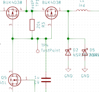 |
| final circuit |
The current polarity problem
When the sun is up the solar panel's output voltage is somewhere between 6V and 12V, which is higher than li-ion voltage. But when sunsets solar panel behaves like LED and sinks current from battery even with voltages as low as 3V. This means that either way the MOSFET is connected at some point in time, the body diode will conduct. To get around this fact that I used 2 MOSFETs in typical back-to-back configuration to fix the body diode "issue".
It doubles Rds(on) and gate charge doubling switching losses and conduction losses. Not perfect but acceptable. I could drive both MOSFETs independently to reduce switching losses a bit (as one would be switched rarely) but then I'd need 2 level shifters and more complex driving logic which I don't think it was necessary.
Voltage level translation
Gate of MOSFET requires <-3V to fully open and >-1.5V to fully close relative to the drain. Source is approximately equal to the solar panel voltage that as per specification can be anywhere between 6V and 12V. If we translate thresholds that gives us <3V for open and >4.5V for closed at 6V and <9V for open and above 10.5V for closed at 12V.
Thresholds are higher than output of logic IC I used (as it's powered directly from li-ion) so I can't use it directly to drive gate. Clearly some voltage translation is required for certain. Simplest possible solution is using just Q5/R3 combination. Q5 pulls gates low, closing switch, then Q5 opens R3 slowly pulls gates up opening switch. Closing is almost instantaneous as Q5 can sink a lot of current, taking the entire gate charge nearly immediately.
Opening is slow, transition time between 2.5V and 1V is roughly one time constant (91.6% of tau for pedants) so it's inversely proportional to R3 value. On the other hand power losses are also inversely proportional to value of R3 (solar voltage/R3 * duty cycle). Noticeably there's some optimal value when MOSFET already switches fast enough yet R3 doesn't dissipate that much heat. I did math for conservative 100khz switching frequency and resistor already got unreasonably large. I need something else.
If I'd leave only R3 and C9 I could still switch MOSFET, with very sharp edges (speed defined by logic drive strength) but there would be some limitations. The "must-haves" are as follows: the average gate-source voltage has to be zero, since R3 shorts any DC offset, logic swing can be as low as 3V and MOSFET may need as much as -2.5V to open duty cycle, which would be limited to 1/6 ~ 17%. This in turn would force maximum inductor current to be over 7 times higher than the average current forcing either unreasonably low charging current or unreasonably high saturation current.
MPPT
Now let's talk about MPPT. MPPT stands for Maximum Power Point Tracking. Its idea is as follows: there's spot on V-I curve of the solar panel where the power output is the highest. Additionally, we should adjust parameters of SMPS in a way such that it tracks this maximum power point.
All tracking algorithms measure power delivered by solar cell and how it changes with different parameters trying to somehow find a global maximum. In this case the only variable is a duty cycle of the switch and consequently, a control loop is as simple as changing duty cycle and seeing, whether the power delivered either increased or decreased. For sure, this only finds the local maximum, but as the curve has just one maximum it isn't a big problem.
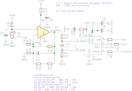
As measuring power delivered is a common denominator let's start by discussing how to do that.
Power measurement
There are 2 ways I came up with:
- Measuring power delivered to li-ion cell by measuring current at the output of switching mode converter, measuring voltage of battery and multiplying them together. As MPPT adjustment time is sub-second and battery charges many hours battery voltage can be assumed constant and power is proportional to the output current.
- Measuring solar cell voltage and current, assuming that the efficiency of a converter is not changing, a lot in usable range of duty cycle (or at least the one which is changing
- slowly enough that it doesn't move maximum power point too much).
Both methods have their pros and cons. The biggest upside of first method is that only one quantity is measured, and as only sign of its time derivative is important the circuit can be as simple as comparing the signal with a slightly delayed signal. The biggest downside is a need to insert the current sense resistor into the power path and have a quite substantial voltage drop on it in order to get an acceptable resolution.
On one hand, method 2., requires multiplying current value by voltage value. Multiplying is complex in both analog and digital world. On the other hand, the current sense resistor can be made much smaller (due to characteristic V-I curve of solar cells) and it can be also used for the peak current mode regulation (it ensures a better stability and much simpler control loop for SMPS).
So what do you think, which one have I chosen? Surprisingly, neither of them. Both solutions waste more power then a simplified method I've chosen. However, in order to understand this concept better, we need to dive a bit deeper into characteristics of solar cells.
Characteristics of solar cells
First let's look at the V-I curve of some solar cell for different irradiation levels.
 |
| source: wikimedia |
We can see that it behaves like the constant current source up to some point, above which the current quickly drops. More important observation is, a dark blue line shows the maximum power point for all curves. As we can see for high irradiation levels (max current >=10mA) the maximum power point's voltage doesn't change much. It's 0.4V @ 10mA and around 0.44V @ 40mA. It's just 10% increase. This means if we liked to set control loop to stabilize input voltage to 0.4V it'd deliver maximum power when there's 25% of max solar irradiation and 92-93% of maximum power when there's full sun. It's not perfect but my simulations showed that it provides a higher average effectiveness than when any other current sense resistor is used.

Comments
Post a Comment