Soalr SMPS Part 5: Control Logic
Till now I only drawn parts of schematic and talked about a mysterious control logic. Now I'll write a bit more how this logic is actually implemented.
Possibilities
"Typical" solution
Output section can be made using one of many commercially available current mode SMPS ICs available. Input section is much more problematic. ICs usually only describe stability criteria and math for standard application and none of them have a stabilization of the input voltage as a typical application. Dedicated MPPT ICs are a few and far between and all of them are notoriously expensive. Also, there's problem of protecting a battery from over charge / over discharge - probably another IC, as well as some delay to turn on LED predefined time after the sunset.
"Discrete" solution
A few EEs much more skilled than me designed LED drive circuits using transistors only, One of examples is: https://www.romanblack.com/smps/a05.htm.
Some of those circuits can be adapted to perform my simplified MPPT control, some cannot be stabilized in such a task. No matter which path we decide to follow, they have efficiency lower than what I'm aiming for so they aren't that suitable for me.
Universal SMPS IC solution
Over the years manufacturers thought about people like me and designed ICs meant for designing custom, non standard converters. They usually contain some PWM generator, error amplifier and uncommitted MOSFET driver/drivers or internal switches. LM78S40 is one example of such IC. This one is better than previous solutions because having so many thing integrated lowers PCB space, radiated noise and standby current. I can't say much more as I haven't explored it fully yet, but my aim is to do it in the nearest future.
Fully custom controller on programmable logic
FPGAs are perfect for generating PWM signals, delaying the output signal and changing control parameters depending on some factors. However, they can't handle analog signals that are used as feedbacks and a battery voltage monitoring for control. That's where greenPAK ICs shine. If we look at SLG46620 that I choose for this project we can see that it has LUTs, counters, latches, digital comparators, delay generators and serial - parallel converter. what's more interesting, it contains 6 analog comparators, 2 DACs, ADC, PGA, bandgap reference and adjustable reference voltage on comparators' negative inputs as well.
The design
On the high level we can divide the design into 3 functional blocks with a few links between.
- Battery monitoring circuit consisting of 2 comparators that turns on or off both converters to protect the battery from over-charge/over-discharge.
- Output converter that monitors LED current using a small shunt resistor and PGA, drives 2 MOSFETs and PWM generation blocks to generate and adjust duty cycle.
- Input converter and diode emulator. Measuring input voltage using 2 comparators, lower voltage one for stopping solar cell from discharging battery and the higher one used for tracking MPPT point.
Planning everything precisely inside IC I came up with the following diagram:
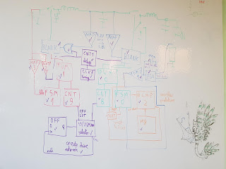 |
| dragon doesn't influence efficiency |
Realizing I have many flip-flops and LUTs free I decided to add logic for the lowering frequency when the duty cycle is very low in order to reduce switching losses a bit.
This ICs are programmed in a graphical environment shared by manufacturer called greenPAK Designer. In ordinary circumstances, it requires a registration to download but as always AUR package came to the rescue. I'm not a big fan of graphical programming environments, but in this case, I didn't have much choice, the only alternative I found is this. It allows to program in verilog, but it doesn't support my hardware and analog primitives are a cumber stone to use.

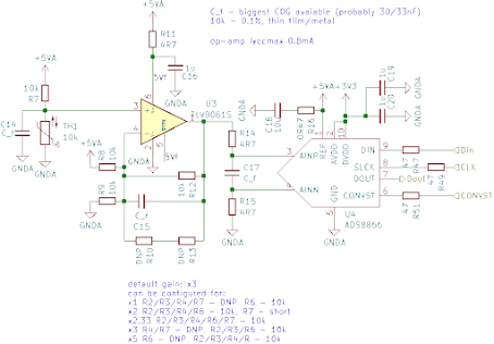
Entire circuit
At this point in time I think it's good to show a full schematic integrating all parts together.


Comments
Post a Comment