qpass or story of how to kick sand
So what this story is about?
Qpass is a method of measuring weight of small mass by depositing it on quartz resonator and measuring changes in electrical properties. Most common are frequency and Q factor changes. Of course because it's sensitive method and requires disposable quartz resonators it's used mostly for very sensitive measurements, hence detected deviation values are very small too, often at the order of sub ppm.
Typical solutions
Most modern commercial solutions use frequency scanning, building frequency or frequency and phase response and searching for peaks and 3dB width. There're few problems with that solution. For once it requires very dense scanning to make sure you find basic mode and not spurious ones. Phase measurements help in finding "missed" resonances but requires more complex analog frontend. Big upside of this method is that one finds interesting mode they can just scan very small range to track Q and resonant frequency.
Another sometimes used solution is to make oscillator out of crystal resonator and reference it's frequency to some reference. It was mostly used in old day to measure deposition thickness of vacuum sputtering. It's simple but reliable only if one adheres to very specific regime. The deposited substance has to not load crystal too much, otherwise it may jump to one of spurious modes. The oscillator itself has to be frequency range limited or quartz has to have specific properties to reduce risk of chaotic operation (more about chaotic operations here).
My task
So what was my task I hear you ask. I was tasked to design some way of measuring either frequency or Q factor in a way worth 21st century. At first I though about impulse excitation but it seemed impossible. In real life perfect impulses don't exist, Dirac delta is not realizable in our physics. The closest alternative with wide and smooth bandwidth is step. Perfect step is integral of impulse, which means it has spectrum rolling off at 1/f. Real life electrical impulses have finite duration, further limiting energy available in high frequencies. Quartz resonators have high Q, which implies very low bandwidth, hence they'll collect very little of pulse energy. Additionally because they resonate very long time they can't be loaded in any way, otherwise external circuit will dissipate their energy influencing Q measurements. We can't use very high voltage as that'll destroy resonator so output signal is inherently limited.
If there was only another way to get energy into crystal ... I experimented with physical "kicking" resonator but that proved too unreliable and induced piezoelectric effect in capacitors all around. At last I tried laser. As you know by now i love quick, pulsed lasers. They can deliver a lot of energy in comparably tiny amount of time. My experiments didn't go too far before I realized that few thousand dollar, big machine is in opposition with my design goals of small, mobile and cheap.
Ruling out impulse excitation I had another idea. what if I could combine benefits of both popular methods. Take "automatic" frequency finding out of quartz oscillator and combine it with possibility of Q measurement from frequency scanning.
My initial solution
Every oscillator is made out of 2 parts. The amplifier that provides gain and phase shifting element. In order for this system to oscillate 2 criteria have to be met:
- the amplitude criteria, which states that total loop gain has to be >=1
- the phase criteria, which states that total phase shift that loop provides has to be 360°
Phase criteria is met by crystal resonator at any of it's resonant modes: both main and overtones as well as spurious. Amplitude criteria is met by every mode which has losses smaller than amplifiers gain. Assuming then that we can step gain of amplifier we can find exactly Q of least lossy mode.
Problem is with time of measurement. Simple stepping of gain one by one would take ages. Assuming we want ppm resolution every step would take few ms to get to steady state and entire scan minutes. Fortunately we can use clever tricks and computing power of modern microcontrollers to make this method considerably faster.
Oscillation criteria talk only really about steady state. Fortunately we can reshape them a bit to specify dynamic of system:
- always when loop gain is smaller than one oscillations diminish and when it's higher they build up.
Using binary search first few tests are quick as selected points are far from minimum required gain hence quick oscillations buildup and reduce search space considerably. Further refinement is to track Q factor by changing gain in a way that tries to sustain amplitude of oscillations. As amplitude is integral of gain "error" resolution can be arbitrary increased simply by extending window in which it's measured.
Amplifier. It needs to have precise control of gain and very small phase shift. Why minimal phase shift? Because total loop phase shift has to be 360° so everything that is introduced by amplifier moves resonator away from series resonance. Because phase shift is additive across multiple stages of amplifier it's important to have as few as possible. Additionally it'd be good to have some frequency dependent element in loop to be able to reduce gain at certain modes, allowing for measurements at other modes.
 |
| core of my design |
Due to legal reasons I can't show entire circuit, but this is core. I ended up with simple, intricate circuit. Single differential pair with gain controlled my emitter current mirror, with possible frequency selective elements in base of right transistor. Most important arguments that lead me to this choice are:
- differential pair can operate near ft, which for modern transistors can be easily in tens of Ghz, reducing phase shift at tens Mhz range (resonant frequencies of common quartz) to sub 1°
- In contrary to other solutions this one provides precise and linear control over amplifier's gain. With 24 bit sigma-delta DAC wide scanning range with sub ppm resolution can be achieved
- Frequency dependent elements are not in signal path hence there's no problem with impedance matching
- amplitude dependent gain due to tanh transfer function
Amplitude dependent gain allows for one more resolution increasing trick: steady state amplitude depends on how much gain had to be "stolen" by tanh to get to unity gain allowing for measurements between control codes of DAC.
Second solution
Project has really tight deadline of just 6 month, 2 of which I spend abroad. So to make sure something will work I decided to develop second solution while waiting for PCB. Funny enough I returned to electrical impulse excitation. To make it work I need to achieve two things at once:
- "kick" crystal with fast step
- AC short it while measuring loop current
Getting sharp step is easy enough, I already developed sharp pulse generator based in differential pair, problem is in low output resistance. Because differential pair is basically controlled current source the lower the output resistance the lower the amplitude. Knowing that it's not viable solution I searched for CMOS gates that have steep enough output pulse and low resistance. In the end I settled on 74ACT00, quad nand with all gates paralleled. It have me sub 5R output resistance with 1-3ns edge time.
For detection part I was thinking between plain old small shunt resistor for current measurement or transimpedance stage on op-amp. Shunt resistance applies constant resistance over entire frequency range. Transimpedance stage lowers feedback resistance by factor of (f/GBP)^2. Even with fastest, 500Mhz, voltage feedback op-amps factor is as low as 400 for 25Mhz resonators. Then there's a question of op-amp's phase shift that shows up as frequency dependent capacitance at the input...
In the end I selected transimpedance stage reasoning that I want simpler analog path and that all higher order effects can be compensated later in software. Another important factor is parallel capacitance of quartz feeding some of the pulse directly into stage. In transimpedance stage it can be mostly removed by capacitively feeding part of pulse into positive op-amp's input.
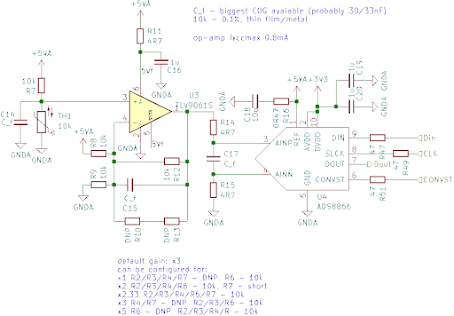
 |
| my impulse circuit |
As you can see from my notes I did some math regarding anticipated output voltage but I couldn't believe them, so I settled on 2 stage amplification only. In testing I had to increase gain of stages to get meaningful output signal.
 |
| don't look at scale, it was set for 10x probe |
As you can side I made it work in the end.
Final notes
As you can see in this article I only focused on exciters that get some response from resonator, later I'll talk about processing this response to get any meaningful information from them, and it's not easy!
Comments
Post a Comment