Posts

All ways to generate symmetrical rails from a single SMPS
Image
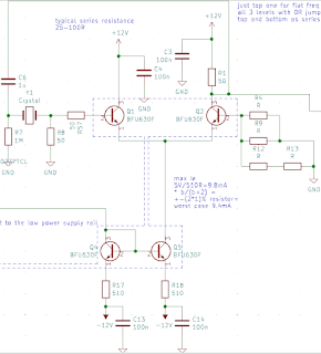
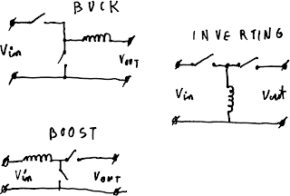
 Introduction While digital systems are increasingly taking over the world, analog circuits are still used in many places, especially in musical equipment. Most of these devices use symmetrical power rails to simplify internal construction. While such approach is indeed good for devices powered from mains with a transformer, it fails short when supplied from a single DC source like battery. In a current world where many devices are getting smaller and more portable, this design philosophy becomes a limiting factor. While we can't change already created devices, we can create a simple switching mode power supply to generate symmetrical power rails from a single DC source. Theoretical implementations There are many ways to generate multiple output rails from a single DC source. Listed in decreasing popularity:  Flyback converter with multiple secondary windings Two independent converters (inverting and buck or boost) Inverting converter based on coupled inductor with rectifier p...
External Cavity Diode Laser - part 2: electronics

Image
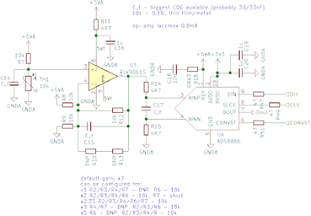
Introduction In previous part I talked about optical part of ECDL controller. I mentioned requirements for tight control of temperature of all elements involved. In this part, we'll discuss what electronics is required to achieve that. Requirements Millikelvin resolution measurement of temperature of both internal baseplate and laser diode Precise regulation of injection current Driving Peltier modules in heating and cooling mode with 16 bit resolution USB control simple power supply requirements 1. Precise thermometer There are three main ways to measure temperature: using thermoelectric effect in thermocouple using semiconductor dependence on temperature, most often employed in integrated thermometers using thermoresistive effect in thermistor  Thermocouple signal is very low, so it's hard and expensive to design an amplifier with low enough internal noise to maintain mK resolution. What's more important, thermocouple effect happens on all material changes, which requires...

External Cavity Diode Laser - part 1: optical path and mechanical design

Image
 Introduction External cavity diode laser (ECDL) combines benefits of laser diodes and DPSS lasers. The semiconductor chip provides easy to pump, efficient, high gain medium while the external cavity allows tailoring device performance.  Wavelength selective elements, like diffraction gratings or etalons can be added to the resonator to reduce emission spectrum, saturable absorber can be added for mode-locking, partially reflective mirror in conjunction with RF modulation can be used for frequency comb generation and many more. In this article, we will try to design simplest, ECDL that'll be used in future experiments so state tuned! How it works There are many great internet sources describing how ECLD works, so let's just quickly recap. Out of the box laser diode has relative wide emission bandwidth, usually around 1-2nm. This is because the gain bandwidth of diode is relative wide and the resonator works with relatively weak coupling (output mirror has reflectivity of 3...

Digital emulation of analog comparator

But why? Recently, I decided to implement digital emulation of all my current eurorack modules . That way, I'll be able to share them with everyone to play and experiment before they decided to spend cash on an actual module. There's just one big obstacle in a way - SSH uses analog switches driven by comparators in the signal path. While analog switches can be nicely modeled with multiplication, I was unable to find any publications regarding accurate modeling of comparators. Naive approach The simplest way to try to model an analog comparator would be to use a digital comparator. Unfortunately, while simple, this solution suffers from a great amount of aliasing. It can be thought of in two different ways. One is that digital comparator outputs bandwidth unlimited step at the output leading to great aliasing, another is that digital comparator works in discrete time so can't sense when exactly the threshold has been crossed. Oversampling One, often thrown around, method of ...

orange 607nm on Pr3+

Image
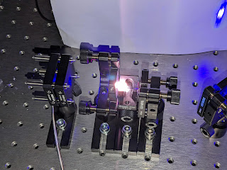
The inspiration I'd like to share the details of my journey in acquiring an orange laser for my desk. Some of you might know that I initially dabbled with dye lasers. While they are impressive in terms of the range of colors they can produce (with a single dye capable of spanning half the rainbow, and a mixture of dyes covering nearly the entire visible spectrum), they come with the drawback of requiring Q-switched pumping or a complex setup involving dye jets and recirculation. These setups tend to be neither compact nor quiet. Furthermore, every lab I visited with dye lasers seemed to have tables and floors stained with dyes, creating a fluorescent environment. Clearly, I needed to explore alternative options. Another options Ideally, using a laser diode would be the best solution. Unfortunately, due to technical limitations, there are no laser diodes available between 525nm and 630nm at room temperature.. The AlGaInP have quite high temperature dependence of up to...

Behind the scenes of ModuGlow

Image
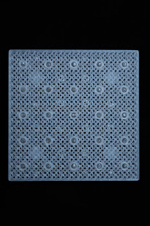
 What is ModuGlow?  ModuGlow is modern, modular, organic lamp that can be anything between night lamp to art sculpture. It's built from 10x10cm panels containing 25 blinking bulbs. It can be stacked in 2 axis to provide arbitrary size lamp. Video showing 2x2 combination working. Neon behavior Neon bulbs exhibit S type dynamic negative resistance. If you understood last sentence feel free to skip this paragraph. Negative dynamic resistance is a behavior of some electric circuits when with increasing current current decreases or the other way around with increasing voltage current decreases. In neon bulbs it manifests itself between strike and maintain voltage. When bulb strikes the voltage starts to drop due to series resistor. Dropping voltage makes bulb want to draw more power further lowering voltage until negative resistance region ends near maintain voltage. That way bulb "turns on" at higher, striking voltage while "maintains on" at lower maintaining voltag...

Implementing FIR on RP2040's PIO

The purpose of this blog post is to describe the process of connecting a MEMS microphone with PDM to a microcontroller, and the steps taken to optimize the PDM-to-microcontroller data processing for better performance. Introduction In my latest research I'm in need to connect MEMS microphone with Pulse Density Modulation (PDM) to micro-controller to evaluate their parameters. In contrary to more popular Pule Code Modulation (PCM) that sends data at reasonable sample rate (40-192khz) with wide words (8-24 bits) PDM sends one bit stream at Mhz sample rate straight from sigma-delta modulator. To do anything useful with this stream it needs to be decimated to lower sample rate while increasing word width and filtering out high frequency noise. My microphone generates PDM stream at around 3Mhz. I want to downsample it around 40khz to feed my "standard" software DSP to have enough time to process data. Why? Decimating signal is as simple as selecting one sample every N and d...

PCB holder 2

Image
 As promised this is update to last post about our PCB holders. Technical difficulties It turns out that if I want tapped hole every 10mm that's a lot of tapping. Additionally tapping steel is quite hard, especially with such small tap. Most companies decided that they don't want to do such job, one that agreed is research institution so I guess they're used to nontrivial requirements. After some negotiations we got price of almost 5k euro for 300x300mm sheet. That's a bit too much for this project. Required changes My changing steel to aluminum and moving holes onto 15x15 grid we considerably reduced required engineering time. After initial testing it turned out that 15x15 hole spacing is more than sufficient, but swapping to aluminum means magnetic mounts are no longer an option. I guess it's low price to pay to reduce manufacturing cost to 740 euros. plates when they first arrived in our lab   Designed mounts We designed few mounts for plates to mount things on t...

PCB holder

Image
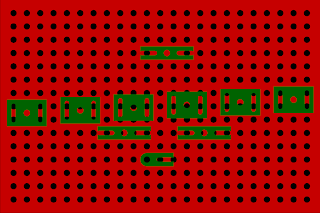
 Today's post will be quick one. I got too irritated by all PCB clamps that don't all work all too wall so I decided to make my own! Inspiration came mostly from optical tables we use all around our labs. I decided to make thin, heavy base plate with M3 holes every 10mm and adapters to be able to mount support wherever I want. The design looks like this: quick render of design Before commiting to expensive and long process of getting them milled from steel plate I decided to make sure that it's as useful as I think. For that I 3d printed prototype out of PLA. I wanted to make it out of black PLA but part way through filament ended and I had to quickly switch to orange. This is how it looks assembled: PCB mounted for soldering everything prepared for mounting PCB It make look more complex than usual clamps to use but keep in mind that if board has screws on 10mm raster then spacers can be screwed directly into base plate. Additionally thanks to modular design boards can be m...

qpass or story of how to kick sand

Image
 So what this story is about? Qpass is a method of measuring weight of small mass by depositing it on quartz resonator and measuring changes in electrical properties. Most common are frequency and Q factor changes. Of course because it's sensitive method and requires disposable quartz resonators it's used mostly for very sensitive measurements, hence detected deviation values are very small too, often at the order of sub ppm. Typical solutions Most modern commercial solutions use frequency scanning, building frequency or frequency and phase response and searching for peaks and 3dB width. There're few problems with that solution. For once it requires very dense scanning to make sure you find basic mode and not spurious ones. Phase measurements help in finding "missed" resonances but requires more complex analog frontend. Big upside of this method is that one finds interesting mode they can just scan very small range to track Q and resonant frequency. Another someti...