Posts

soalr SMPS part 6: the prototype

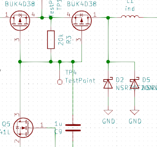
 At least we got to this stage. All designing work is done, PCB is designed, parts arrived, time for assembly. As usually it wasn't smooth sailing. Assembly When assembling I run out of 22uF 0805 capacitors. Due to global chip (and other electronic parts too) shortage then only models available were 50 cents / pcs. With 12 caps on board that'd be 6 euro just for filtering caps. Not in hackers spirit. 10uF 0805 caps I was able to acquire at 3.5 cents / pcs figuring I can just stack two on top of each other to get better filtering. My chosen MOSFET wasn't available and I had to switch for BUK4D38 which has both higher gate charge and Rdson. Finally silicon wafers' price spiked increasing solar panel prices few times. I hope they'll drop soon but in meantime I want to make it going on panels I already have and what I have is totally incompatible with original project requirements (19V MPPT voltage) so will have to work far away from it's maximum power point. First ...
Active Eurorack Busboard Part 2

Image
Protection circuitry Having all parts selected it was a high time to draw schematic. Let's start the discussion with the protection circuitry. All output rails have to be protected against reverse polarity. In case someone shorts positive and negative power rails together one over-current / short-circuit protection will turn converter off before the other one possibly leading to rail reversal. Protection is as simple as putting beefy Schottky diodes normally in reverse polarity on all 3 power rails. Another possibility is that the user connects 2 busboards together using ribbon and he doesn't connect 24V rail to one of them. In that case converters will be back powered. LMR50410 starts with pre-biased output without any issue but MAX1757* doesn't have clear specifications in this context. To protect it I decided to "create" 24V line from 12V and 5V lines using Schottky diodes from output to input of positive voltage converters, just like you protect linear regulat...

Dye Laser Part 4: Getting Anwsers

Background Thanks to help of my friends I managed to contact a very helpful PhD working at Warsaw University, Faculty of Physics that researches ultrafast laser pulses and their use. She got interested in my project and we spend over 6h measuring chlorophyll in various ways. Measurements Because 2 high school students also came to learn about spectroscopy we started with redoing excitation ans emission measurements. As expected we found 2 peaks at the excitation spectrum each came with corresponding 2 peaks in the emission spectrum.  Then we measured lifetimes of each of the transitions. 420nm excitation resulted in 5.36ns lifetime for both 672 and 729nm emission. 468nm excitation resulted in 2.94ns lifetime for 657nm emission and a double exponential decay for 716nm. This double decay was around 90% 2.94ns and around 10% 5.8ns.  As a sidenote: Generating sub 1ns, tunable laser pulses is "simple". It was just a matter of using  Q-switched Nd:YAG going through nonlinear cr...

Soalr SMPS Part 5: Control Logic

Image
 Till now I only drawn parts of schematic and talked about a mysterious control logic. Now I'll write a bit more how this logic is actually implemented. Possibilities "Typical" solution Output section can be made using one of many commercially available current mode SMPS ICs available. Input section is much more problematic. ICs usually only describe stability criteria and math for standard application and none of them have a stabilization of the input voltage as a typical application. Dedicated MPPT ICs are a few and far between and all of them are notoriously expensive. Also, there's problem of protecting a battery from over charge / over discharge - probably another IC, as well as some delay to turn on LED predefined time after the sunset. "Discrete" solution A few EEs much more skilled than me designed LED drive circuits using transistors only, One of examples is: https://www.romanblack.com/smps/a05.htm . Some of those circuits can be adapted to perform ...

Soalr SMPS Part 4: Input Section

Image
Intro  I decided to make the input power path simpler than in the output section. Instead of a complex semi-synchronous rectification I opted for a simpler Schottky diode rectifier. But apart from that everything else got more complex. final circuit The current polarity problem When the sun is up the solar panel's output voltage is somewhere between 6V and 12V, which is higher than li-ion voltage. But when sunsets solar panel behaves like LED and sinks current from battery even with voltages as low as 3V. This means that either way the MOSFET is connected at some point in time, the body diode will conduct. To get around this fact that I used 2 MOSFETs in typical back-to-back configuration to fix the body diode "issue". It doubles Rds(on) and gate charge doubling switching losses and conduction losses. Not perfect but acceptable. I could drive both MOSFETs independently to reduce switching losses a bit (as one would be switched rarely) but then I'd need 2 level shifter...

Active Eurorack busboard

Image
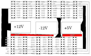
Task  Last summer I was asked to design busboard for 3U 42HP eurorack case. For those of you who have no idea what it is I explain. Eurorack system uses 10 (less common) or 16 (more common) pin IDC ribbon to transfer it's power. It requires symmetrical 12V and sometimes 5V. 1HP is 5.08mm so 42HP case roughly 213mm in size. source: doepfer.de Requirements As with all project I got set of requirements that contradicted each other partially: fit into shape of case, allocating space for 28 M2.5 mounting holes provide at least 0.8A on all 3 output rails, 1A on positive rials preferable lowest possible output noise single 24V input supply possibility of daisy chaining cooling to top side of PCB Initial plan First I started thinking that I can simply use linear regulators for 5V and 12V, but after finding out that I'd need to dissipate over 23W of heat worst case it became immediately obvious it's not the way to go. Case is plastic, without many ventilation holes and without force...

dye laser part 3

Image
 Dye Death  Regarding the experiment described in the last post. We tested 5 power levels : 0.1W, 0.2W, 0.4W, 0.8W and 1.6W with the same power * time product of 30 sW. All samples degraded the same, which suggests that it is a photochemical reaction and not a thermal decomposition. It's much better to see this in real life than on the photos, but for those that are curious I'll attach it below. Looking up in the appropriate literature the most probable explanation is an oxidation of molecules excited to triplet state by the oxygen dissolved in to the solution. This also explains why sample in basement held in such a good state. It was enclosed in flask with air tight, ground seal. extreme left and right are without the laser exposure, different power levels in between What's interesting though, is that the dye died above, as well as at the level of laser beam but not below. This means that the amount of heat generated is enough for the convection in order to mix the fluid ...